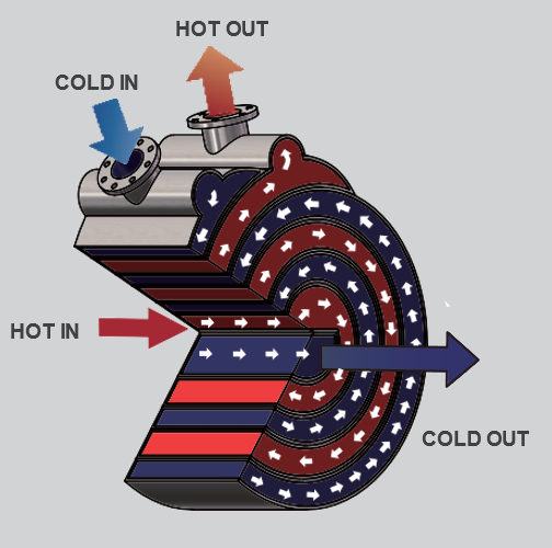
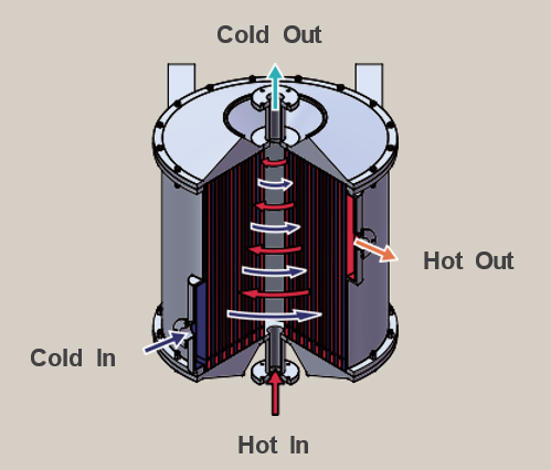
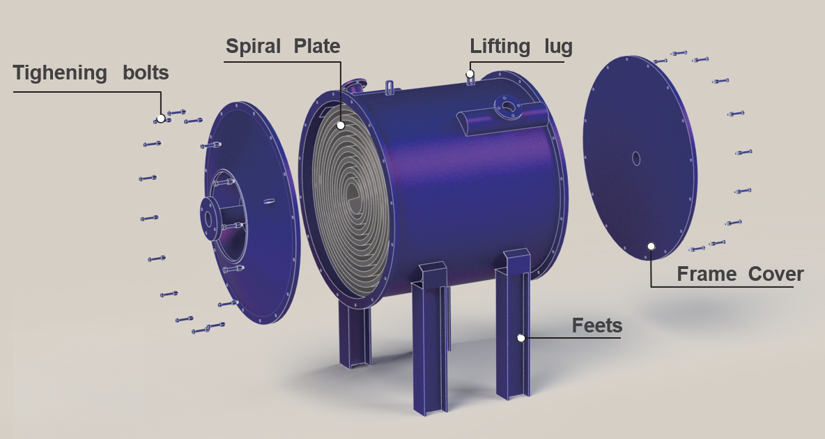
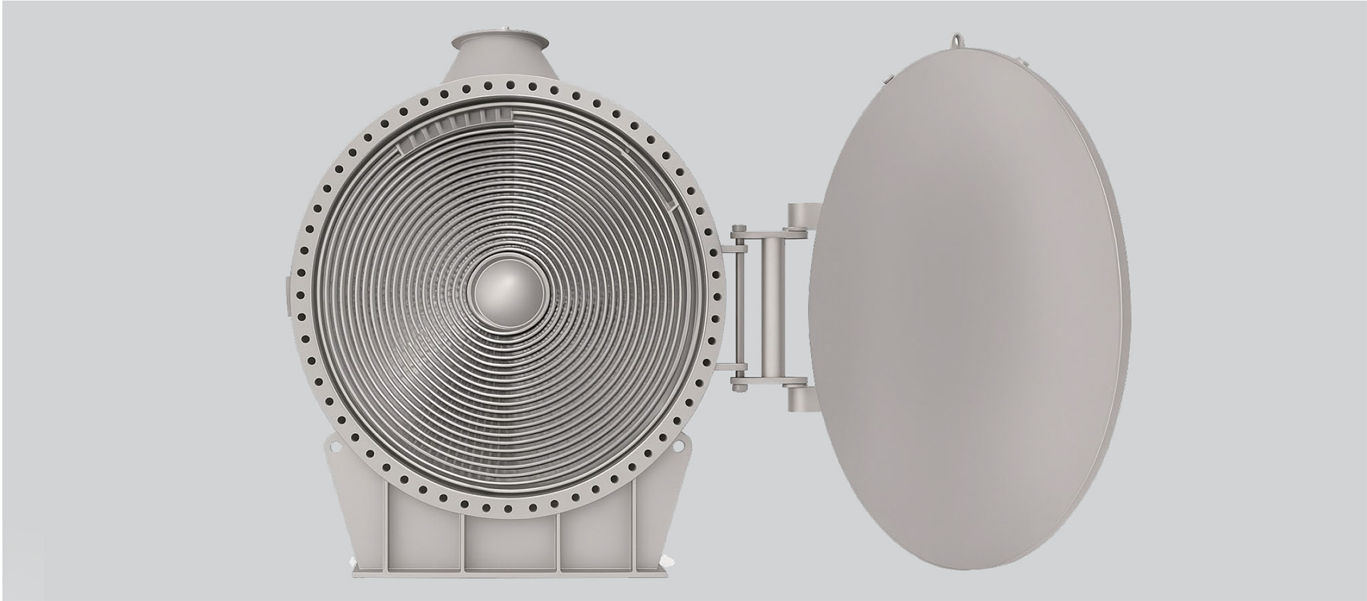
The spiral heat exchanger features two concentric spiral flow channels that create a true
counter-current flow. Typically, the hot fluid enters at the center and flows outward toward the periphery, while the cold fluid enters at the edge and flows inward toward the center. This counter-flow configuration ensures highly efficient heat transfer.(Figue 1)
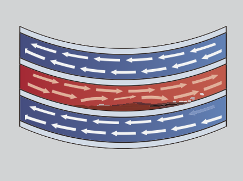
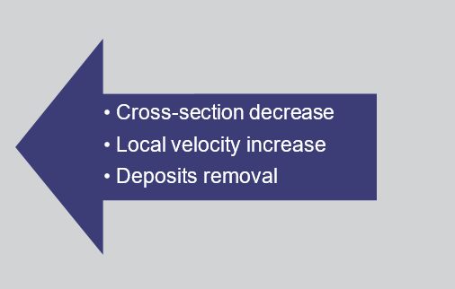
Thanks to the continuous, single-channel design, the flow remains uniform with no risk of bypassing. This layout significantly reduces fouling and allows for close temperature approaches—even temperature crossing—resulting in superior heat transfer perfor-mance compared to many conventional heat exchangers. Unlike multi-pass designs, the spiral geometry prevents flow diversion due to partial clogging, ensuring consistent operation.
• Spiral Plate Width: 200 to 2000 mm
• Spiral Plate Thickness: 2.0 to 6.3 mm
• Channel Spacing (Plate Gap): 5 to 38 mm
• Heat Transfer Area: 1 - 500 m² per unit
• Shell Diameter: up to 2500 mm
• Design temperature: -100°C to 400°C
• Design pressure: Full vacuum to 40 barg
• Maximum heat transfer Area: 900 m2
• Shell material: Carbon steel, SS 304/ 316L
• Spiral Plate material: Carbon steel, 316L/304, Ti, 2205 Duplex, Titanium, Nickel alloys
• Petrochemical
• Refinery
• Steel making
• Pulp and paper
• Metal/ore processing
• Wastewater treatment
• Pharmaceutical
• Vegetable oil processing
• Distillery
Materials of Construction
• Standard: PVQ carbon steel, 304, 316L, Duplex 2205
• Higher Alloys: 904L, 254 SMO, AL6XN, Nickel Alloys, Titanium
• Built-in self-cleaning function
• Excellent heat transfer performance
• Efficient utilization of waste heat
• Uniform flow with no blockage